Making the power supply
Why we need an extra circuit
You could just connect the buck converter directly to the ignition switched 12V and then to the computer, but it is generally not good for computers if they just lose power instead of shutting down properly.
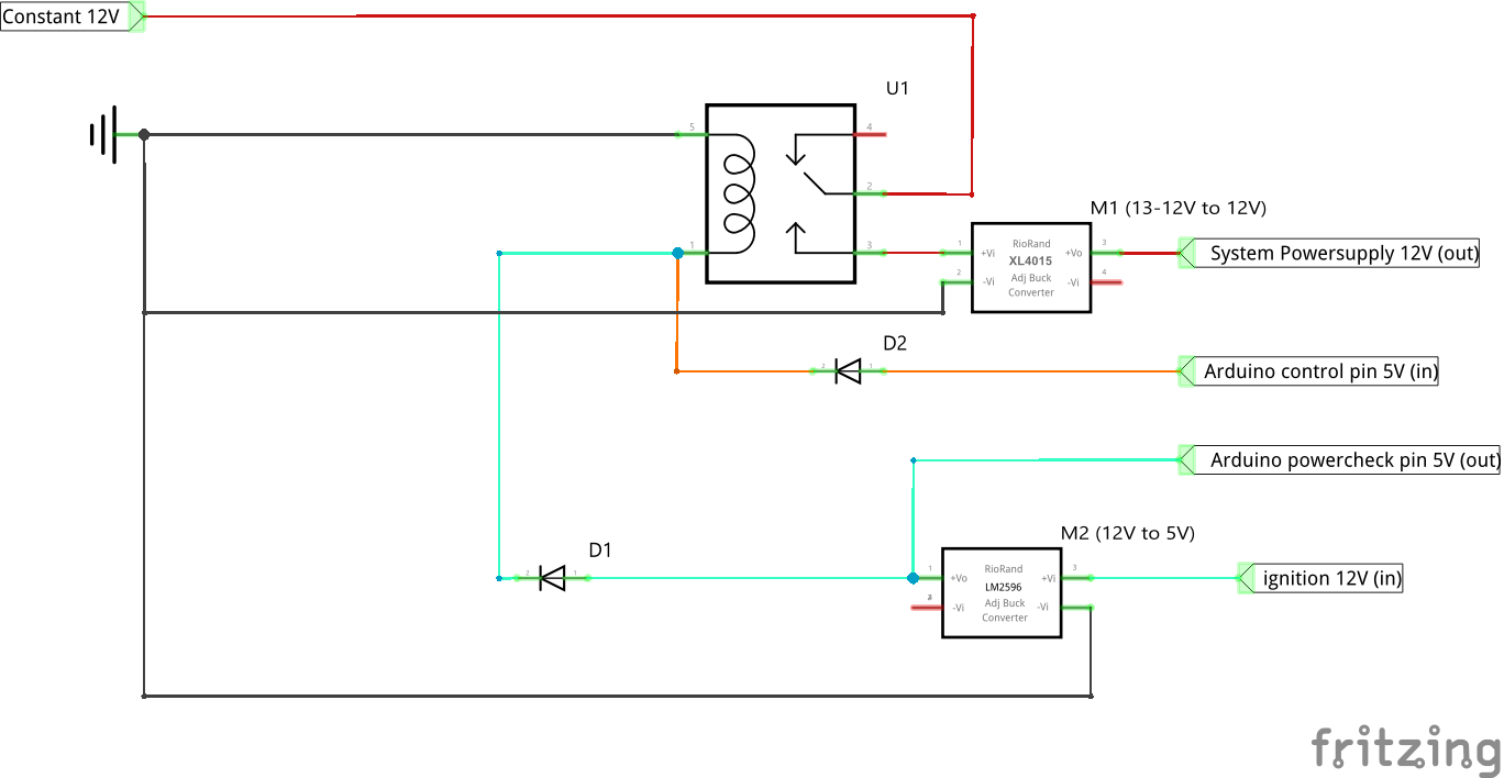
Circuit diagram
The circuit I used works like this:

You can probably also use a voltage divider instead of the LM 2596
We have a relay that switches the constant 12V, which is going to the buck converters (the XL4015 DC-DC and LM 2596S DC-DC). The ignition switched 12V also goes through a buck converter to convert the 12V to 5V so that it doesn't break the relay.
So if the ignition 12V gets turned on the relay activates power to the system this starts an Arduino that gives power to the relay. So if the ignition now gets turned off the relay stays on until the Arduino gets the signal to turn it off.
We also have one wire after the down-stepped ignition voltage that goes to the Arduino so that it knows if the ignition is on or off.
To find which wire is what please use your car's manual since it can depend on the model country and some other factors.